Installing a 1G Cam Angle Sensor in a 2G
The Good
- Magnus Motor Sports revealed
to the world their method
of dealing with the crank angle sensor when installing a 6 Bolt 1G motor
into a 2G. A 1G cam angle sensor, (CAS) can be used to provide BOTH the
necessary cam and crank signals to the 2G ECU. Using this method
eliminates the machining
work that otherwise would be required to put a 2G oil pump and crank
sensor on a 6 bolt
block.
- This also means any Turbo 2G can use the 1G CAS on a stock motor to
adjust the base timing. Timing can be used for good as well as
evil. Increase your timing correctly and you can improve pull everywhere
while lowering EGT levels. A modest increase of +3 to +5 deg on pump gas
is good with minimal risk. Race gas means more safety margin to burn, so
more timing to increase.
The Bad
- It's not California SMOG legal to increase base timing. (so be responsible ;-)
- Go too far, and you run out of safety margin. The ECU will pull
timing when it hears knock, but if your safety margin is all gone, knock turns
to deadly detonation, and the ECU can't do a thing to prevent it. All
the while, you will be looking at your EGT gage thinking, "hey, it never
got hot, why did my motor blow up?"
- Reported problems range from none, to annoying, so be aware. At
the time of this writing the most common glitch is an increase in CEL's.
The most likely CEL to occur is "Random Misfire" Possible problem
sources for phantom misfires are intermittent electrical connections and/or
noise in an unshielded wiring harness, harmonic vibrations in the
timing belt system, or a bad CAS. OBD-II 2G ECU's were designed to
detect misfires from a sensor reading directly from the crank. A simulated
crank signal from the CAS may not be accurate enough for some ECU's.
- For 6-Bolt 1G motor into a 2G: If the timing belt tensioner system from a 1G is
used, a timing belt tensioner tool can not be used. This means it is
more difficult to swap cam's, or remove the head as the entire timing belt
cover will have to be removed to re-set the hydraulic tensioner.
The Ugly
- There isn't really any ugly. Most drive-ability issues can be ironed out.
Additional info and support is available at the Yahoo
E-mail list.
See http://groups.yahoo.com/group/DSM1gina2g
and subscribe.
Special thanks to Marco at Magnus Motorsports

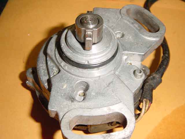
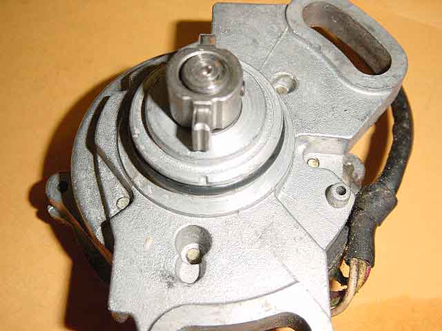
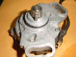
Anatomy of a Cam Angle Sensor:
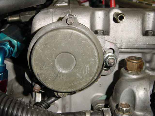
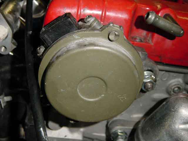
There are three types of cam angle sensor that are known to work. The early
years (89-92) have a metal green/gray cover, use a flat rotating disk with
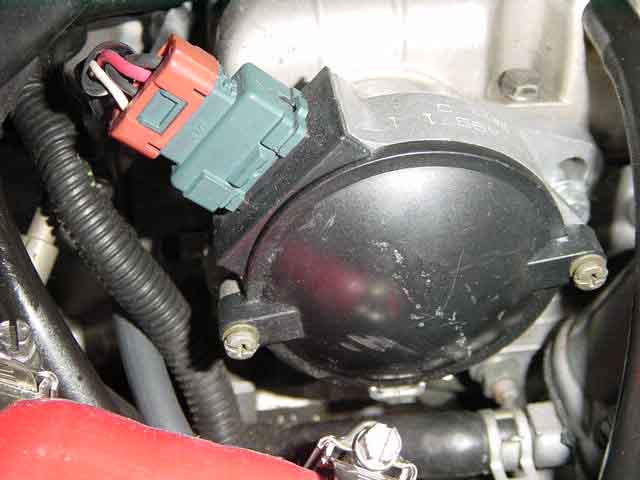
slots, and an optical sensor. The later year sensor (93-94) has a black
plastic cover, uses curved metal plates that rotate through a hall-effect
sensor. The hall effect sensor is physically similar to the technology
used in the 95-96 cam and crank sensors. Theoretically the hall effect
sensor is higher resolution. They all work.
 |
 |
 |
89-90
MD121786
Green Lid, Optical Type, Long Wire Harness |
91-92
MD148855
Green Lid, Optical Type, Plug Harness |
93-94
MD184529
Black lid, Hall Effect Type, Plug Harness |
How do I do this already?
1. Make a wiring harness. Use one of the following methods for your
situation:
95-96 ECU Cars Method 1
95-96 ECU Cars Method 2
97-99 ECU Cars
2. Bend or remove any brackets that would get in the way of the installed 1G
CAS
3. If you have a 2G head, remove your 97-99 CAS, or remove the rubber coated metal cap from the
left end of
the intake cam on your 95-96
4. Rotate the motor to Top Dead Center (TDC) #1 cylinder. The cam alignment
pins will be at 12:00. The timing marks will be lined up at 3:00 on the
exhaust cam and 9:00 on the intake cam. Those two marks will be lined up
directly through the centerline of the cam bolts in the center of the pulleys.
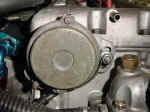
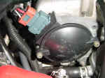
5. Align the marks on the 1G CAS to TDC and Install. Set the CAS at its
mid-range of adjustment.
|
 |
 |
|
Lined up 180 degrees out |
Lined up correct for TDC #1 |
6. Make sure the ignition key is off and the ECU fuse is pulled. At this time
make changes to your plug wires and injector wires if necessary. Connect your
custom
wiring harness to the 1G CAS. Route the harness away from extreme heat
possible noise generators, (spark plugs, coil's, alternators etc.)
Behind/under the intake manifold works fine.
7. Replace the ECU fuse and start the car.
Set the base timing:
1. Connect a timing light to battery power (+ and -) and the Number 1 spark
plug.
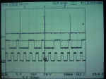
2. Connect a data logger to the car and display timing advance and RPM
3. Allow the car to come up to temp. Coolant 212 deg F, 750 RPM +/- 100,
Fan's should cycle on and off
4. Read the timing from the crank with no load on the motor. Each mark is 5
deg no fans, no lights, no A/C etc.
5. Adjust the position of the CAS until the readings from the TIMING LIGHT,
match the timing advance displayed on the data logger. This is
"stock" advance. If you have a mild setup with stock cam's
you'll pass the smog inspection if your ECU timing and crank timing reads 5 deg +/-3 deg
BTDC at idle
6. Add additional timing at own risk, (Timing light advance) - (ECU advance) =
(Base Timing Shift) see: "The bad"
7. Tighten the 12mm nuts/bolts that hold the 1G CAS
Contact Road///Race
Engineering
13022 La Dana Ct, Santa Fe Springs Ca. 90670
Phone (562) 777-1522 Fax (562) 777-1562
Last Updated 4/07