| Crank Walk | Original
RRE 1G in a 2G |
Cam Angle Sensor 1G in a 2G |
Magnus
Method 1G in a 2G |
E-Mail Support Group |
 |
|
|||||||||
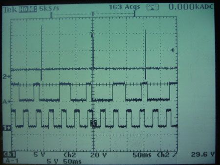 |
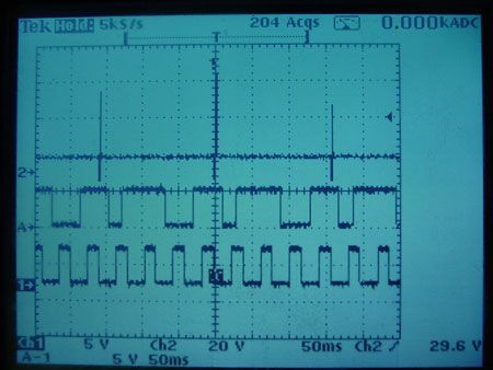
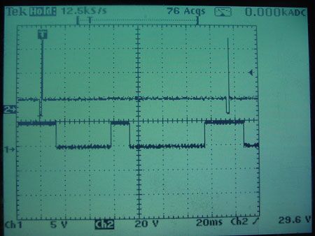
Wave forms seen when a 1G CAS is bolted directly into a 95-96 Eclipse. Note the different location of the trigger for #1. It is just after the short signal. |
|||||||||
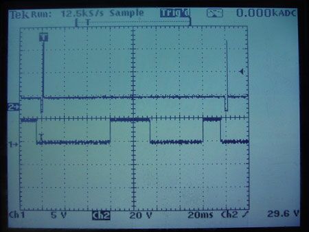 |
Here we are probing the injector for cyl #1, looking for a match. |
|||||||||
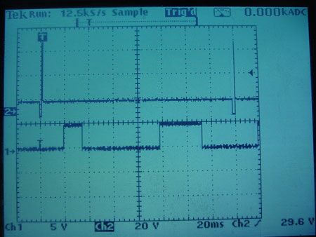 |
Probing #2. This appears to be closest to the stock signal. |
|||||||||
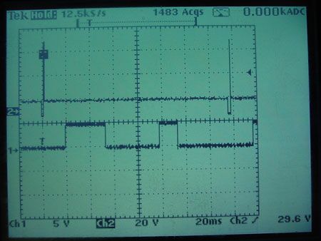 |
Trigger for the signal for injector #3 |
|||||||||
 |
Trigger for the signal for injector #4 |
| Sensor Triggers | |
|
1G Sensor Trigger Plate |
|
|
|
95-96/97-99 Sensor triggers |
|
|
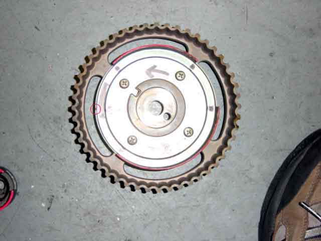
95-96 Sensor trigger
Red circle is sensor location at TDC #1 |
|
|
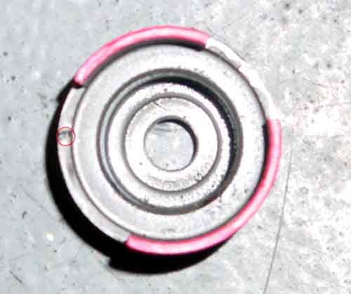
97-99 Sensor trigger
Red circle is sensor location at TDC #1 |
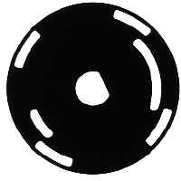 |
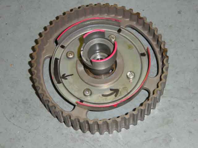
1G CAS trigger disc Outer set of holes is the same as the 2G crank angle sensor. The inner big/small set of holes is the same as the cam angle sensor on a 2G. Rotation is counter-clockwise relative to sensor |
Contact Road///Race
Engineering
13022 La Dana Ct, Santa Fe Springs Ca. 90670
Phone (562) 777-1522 Fax (562) 777-1562
Last Updated 4/04