![]()
| Main Page | Crank Walk | Original
RRE 1G in a 2G |
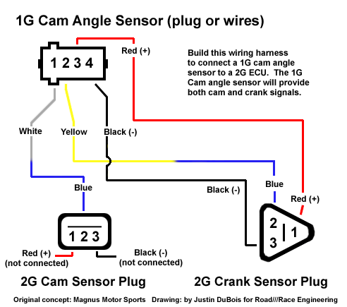
Cam Angle Sensor 1G in a 2G |
Magnus
Method 1G in a 2G |
E-Mail Support Group |
This harness is now for sale if you do not wish to make it your self. See the main 6 bolt swap page.
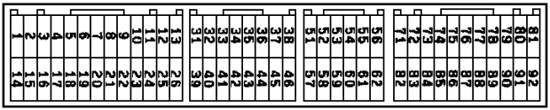
Use the following diagram: http://www.vfaq.com/mods/ecu-harness-2G.html
When removing the pins on your ECU wiring harness be patient and delicate. It requires no force to remove the pins. Consult the diagram in the front of your electrical service manual regarding the proper way to inspect and remove pins. You will need a tiny jewelers screwdriver, (1/16 in) to release a plastic catch holding the pin's in. Use a flashlight and take a good look at the harness before beginning.
Green: Pin 1 is now 14
Green w/ yellow stripe: Pin 2, is now Pin 1
Green w/ red stripe: Pin 15, is now Pin 2
Yellow w/ black stripe: Pin 14 is now Pin 15
The spark coil signal is inverted. Looking at the coils, label each wire A,B,C,D. Change the spark plug wire locations: A is now C, B is now D, C is now A and D is now B. Another way to do this is to change the trigger wires to the coil, (3 wire triangle plug, next to the igniter). Switch the two blue wires. One is blue with red stripe, the other is blue with black stripe. The third wire that remains unchanged is black with white stripe.
Don't take shortcuts in the quality of your connections. Solder everything. Use shielded cable if possible. Do not use wire taps.
Contact Road///Race
Engineering
13022 La Dana Ct, Santa Fe Springs Ca. 90670
Phone (562) 777-1522 Fax (562) 777-1562
Last Updated 4/07