![]()
RRE's EVO X
Engine Control Unit Wiring
Diagram
|
1 |
Intake Cam engine oil control valve |
2 |
No.1 injector |
|
3 |
No.2 injector |
4 |
No.1 ignition coil (ignition power transistor) |
|
5 |
No.2 ignition coil (ignition power transistor) |
6 |
Starter active signal |
|
7 |
Exhaust camshaft position sensor |
8 |
Crankshaft position sensor |
|
9 |
Sensor supplied voltage |
10 |
Throttle position sensor (main) |
|
11 |
Throttle position sensor (sub) |
12 |
Power supply voltage applied to throttle position sensor |
|
13 |
Throttle position sensor ground |
14 |
Intake camshaft position sensor |
|
15 |
Throttle actuator control motor (+) |
16 |
Throttle actuator control motor (-) |
|
17 |
Exhaust Cam engine oil control valve |
18 |
No.3 injector |
|
19 |
No.4 injector |
20 |
No.3 ignition coil (ignition power transistor) |
|
21 |
No.4 ignition coil (ignition power transistor) |
23 |
Exhaust camshaft position sensor ground |
|
24 |
Crankshaft position sensor ground |
25 |
Knock sensor (+) |
|
26 |
Engine coolant temperature sensor |
27 |
Engine coolant temperature sensor ground |
|
30 |
Intake camshaft position sensor ground |
34 |
Heated oxygen sensor (front) heater |
|
35 |
Heated oxygen sensor (rear) heater |
36 |
Engine oil pressure switch |
|
37 |
Evaporative emission purge solenoid |
38 |
Heated oxygen sensor (front) |
|
39 |
Heated oxygen sensor (front) offset voltage |
40 |
Heated oxygen sensor (rear) |
|
41 |
Heated oxygen sensor (rear) offset voltage |
42 |
Knock sensor (−) |
|
44 |
Power supply voltage applied to manifold absolute pressure sensor |
45 |
Manifold absolute pressure sensor |
|
46 |
Manifold absolute pressure sensor ground |
51 |
Fuel pump relay 1 |
|
52 |
Turbocharger wastegate solenoid 1 |
53 |
Turbocharger wastegate solenoid 2 |
|
58 |
Power steering pressure switch |
60 |
Generator G terminal |
|
61 |
Generator FR terminal |
62 |
Generator L terminal |
|
71 |
Throttle actuator control motor ground |
72 |
Throttle actuator control motor power supply |
|
73 |
MFI relay (power supply) |
74 |
Accelerator pedal position sensor (main) |
|
75 |
Power supply voltage applied to accelerator pedal position sensor (main) |
76 |
Accelerator pedal position sensor (main) ground |
|
77 |
Accelerator pedal position sensor (sub) |
78 |
Power supply voltage applied to accelerator pedal position sensor (sub) |
|
79 |
Accelerator pedal position sensor (sub) ground |
80 | OBD pin7 connector (K-LINE) |
|
81 |
ECM ground |
82 |
Power supply |
|
83 |
Throttle actuator control motor ground |
84 |
Throttle actuator control motor relay |
|
85 |
Clutch pedal position switch <M/T> |
86 | |
|
87 |
Mass airflow sensor |
88 |
Mass airflow sensor ground |
|
89 |
Intake air temperature sensor 1 |
90 |
CAN interface (high) |
|
91 |
CAN interface (low) |
92 |
Ignition switch-IG |
|
93 |
ECM ground |
||
| 95 | Cruise control button set input |
96 |
Fuel pump relay 2 |
|
97 |
Intake air temperature sensor 2 ground |
98 |
Intake air temperature sensor 2 |
|
102 |
A/C compressor relay |
103 |
Flash EP-ROM power supply |
|
104 |
Backup power supply |
105 |
Ignition switch-ST |
|
106 |
Starter relay |
107 | Cruise control button set supply voltage |
| 108 | Brake/stop light switch (cruise control system) |
112 |
Fuel tank differential pressure sensor |
|
113 |
Fuel tank differential pressure sensor ground |
114 |
Power supply voltage applied to fuel tank differential pressure sensor |
|
115 |
Fuel tank temperature sensor |
117 |
Evaporative emission ventilation solenoid |
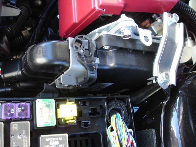
ECM Location:
Contact Road///Race Engineering
13022 La Dana Ct. Santa Fe Springs, Ca. 90670 Tel (562) 777-1522 Fax (562) 777-1562Last updated 2/10mw
Addl info : tephra