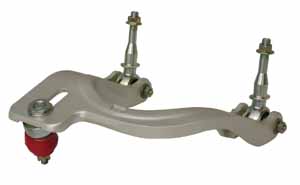
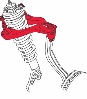
SPC Performance's "Pro Series" is a new line of high-performance forged upper control arms for the 95 - 99 Eclipses, Galants, Talons and Avengers. Constructed of aerospace aluminum alloy these arms are torsionally stiffer than the OE control arm and are anodized for improved appearance and corrosion resistance. One point adjustment for both camber and caster, with the caster adjustment featuring a "positive lock" mechanism designed for high load acceleration and braking. With applications for racing, show and
street tuners, these arms will be the aftermarket's choice when choosing a
high end, light weight replacement arm to correct alignment angles and to
save weight. No longer available
|
INSTALLATION
INSTRUCTIONS
|
PRO SERIES FRONT UPPER ARM (#72030 Right Side & #72035 Left Side) |
|
| 1. Always check
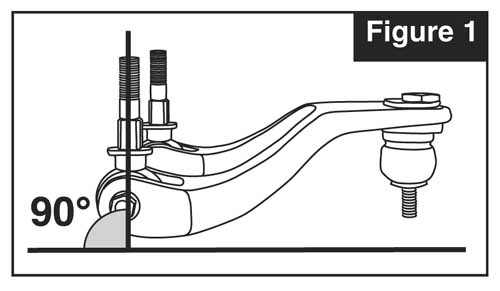
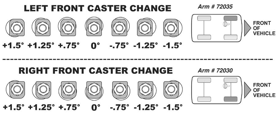
for loose or worn parts, tire pressure and tire wear. 2. Before beginning, Record the alignment readings, determine the amount of caster change needed and raise the vehicle. 3. Raise vehicle by body pinch welds and support with jack stands. Remove front tire and wheel assembly. 4. Remove the cotter pin and nut from the upper ball joint. Break the taper between the ball joint and the spindle and remove the ball joint from the spindle. 5. Remove the bushing support nuts holding the upper control arm to the body. Remove the upper control arm. 6. Set the Pro Series control arm on a flat surface and position the bushing mounts in the position as shown in Fig. #1. Torque the bushing bolts to 22 lb-ft (30Nm). 7. Install one square washer over each bushing shaft with flat edge towards the tire. 8. Install the Pro Series arm into the vehicle, "Right" on passenger's side and "Left" on driver's side, and tighten bushing support nuts to 60lb-ft (85 Nm). 9. If caster adjustment is necessary, loosen and remove the camber adjusting nut and top plate then remove the ball joint assembly from Pro Series arm. Separate the lock plate from the engagement hex and rotate it according to the chart below for the required caster change then press it back onto the engagement hex. 10. Reinstall the adjustable ball joint assembly back into the control arm and replace the top plate. Position the V of the top plate towards the wheel for normal or positive camber change. Position the V towards the engine for extreme negative camber change. Install the nut and lightly tighten. 11. Install the ball joint to the spindle, torque the ball joint to spindle nut to manufacturer's specifications and install the new cotter pin. 12. Reinstall the tire and wheel assembly. Remove the vehicle from the jackstands, and lower the car. Record the alignment readings, determine the amount of camber change needed and verify caster reading then raise the vehicle far enough to have access to the camber adjusting nut. 13. To adjust camber, loosen the adjusting nut and move the adjustable ball joint in or out in the control arm slot to obtain the desired camber reading then torque the adjusting nut to 120 lb-ft (162Nm). Always check for proper clearance between suspension components and other components of the vehicle. 14. Recheck alignment readings, adjust toe, and road test vehicle. |
|
|
|
|