![]()
Sensor Install
1. Tap the hose for the electronic sensor into the hose that runs
from the intake
manifold to the solenoid that controls the fuel pressure
regulator.
On a 1G car it is the center solenoid on the driver’s side
of
the firewall. Remove the double-ended hose connector on
the bottom hose of the solenoid and install the tee in its
place.
For a 2G car it is all by itself on the driver's side of the
firewall.
Cut the hose and install the tee in the hose.
2. Run the wire from the sensor through the firewall. You can poke it
through
boot for the steering column. Use an Exacto knife and cut an
X-shaped
slot through the rubber. Push the hose through this hole. Be careful
routing
the hose under the dash so as not to interfere with the movement of
the
pedals or steering column.
A-Pillar Pod Installation
To mount the gauge pod, mark the desired position first. Remove the
A-pillar
trim gently by un-snapping clips and Velcro. Drill a 3/8”
diameter hole (it will be
covered by the pod) for the wires to pass through. For the 1G cars
the plastic
is very brittle, be careful. Clean the plastic very well with alcohol
or if possible
solvent so the double-sided tape will stick. Do not peel the tape off
or stick the
pod on until the entire installation is complete and tested. You may
also use
screws to help hold the pod on.
Wiring
Red Constant power, 12v. This can be found on the red wire
of
your turbo timer. Otherwise use a test light and probe for
power with the ignition off.
Orange Switched power, on with ignition. On your turbo timer use
either
the green or blue wire at your turbo timer. The cigarette lighter
is also a good place to get switched power. Use the black
wire a the center of the lighter.
White Power for lights. We normally connect this wire with the
orange
wire to switched power. The Mitsubishi dash light wiring
uses
a floating ground system. This makes it so that you cant
hook
the boost light to the dash lights. If you want the light to go
on
and off with the lights you need to connect the wire to the
tail
light circuit. The wire harness that runs along the rocker panel,
under the carpet has this wire. Carefully slit the loom cover
to
expose the wires. The tail light wire is green with a white
stripe,
with dashes on it. It is usually deeper in the harness and
not
the green/white wire right at the top.
Route the wires carefully so they don’t get caught in any moving
parts under the dash.
Use a straightened-out coat hanger to fish the wires from the gauge
area down through the dash if necessary.
|
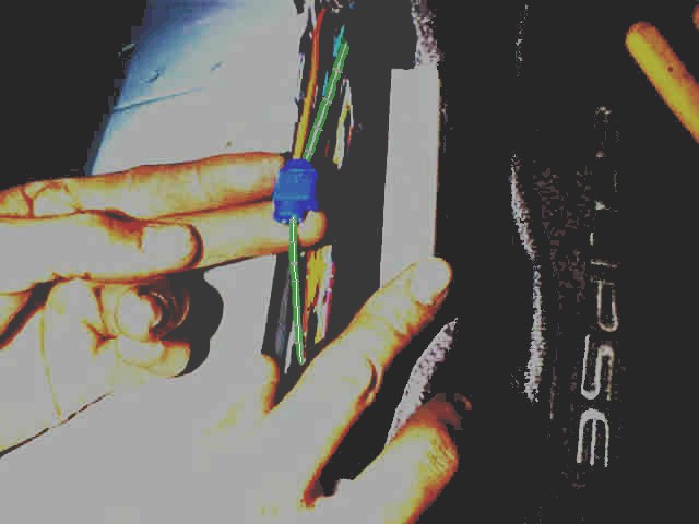
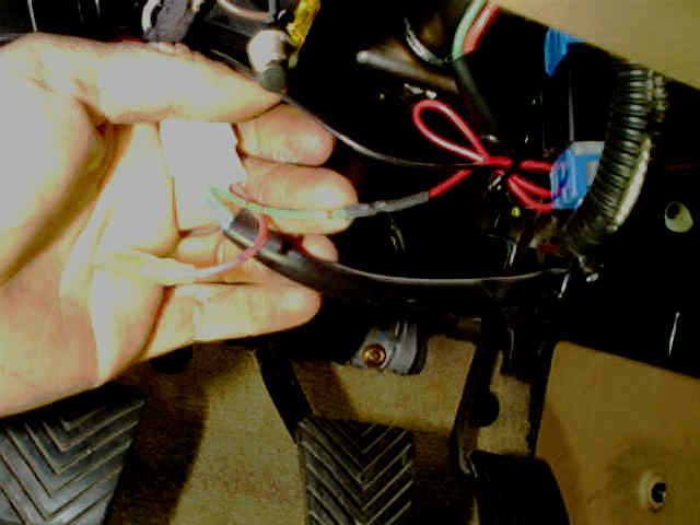
Choosing the tail lamp wire for the GReddy lighting source. |
|
|
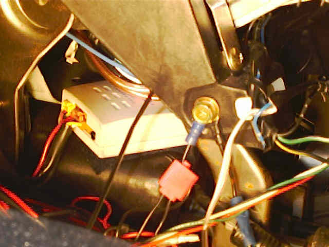
60mm Electronic warning box installed on the center tunnel. |
|
|
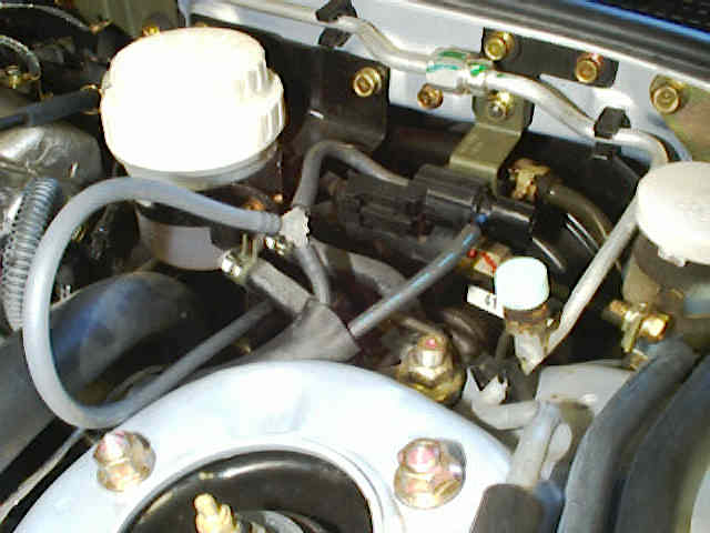
2G Boost pressure source location |
|
|
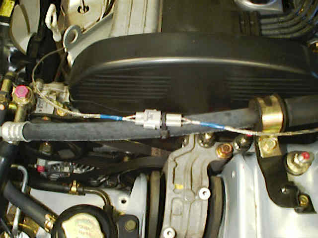
EGT Probe connector secured to the power steering hose on a 2G. |
|
|
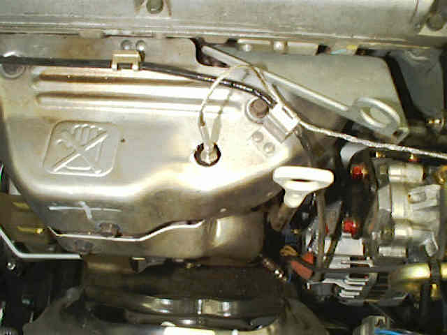
EGT probe installed in the number one runner. |
|
|
|
|
|
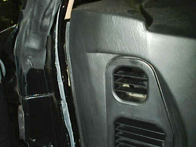
Run the wires down the crack between the dash and the weather stripping from the gauge area down to under the dash. |
|
GReddy 52mm Electronic EGT Gauge Instructions
Sensor Install
1. Cylinder number one runs the hottest so we put the sensor in
the
runner for number one. Drill the manifold with the motor
running;
this will blow out the chips. You do still need to respect the
danger
in the possibility of metal chips getting into the turbo. Drill
slowly,
especially when you are about to break thru. The entire time
you
are drilling and tapping the motor needs to be running.
The only time we had a problem was when we forced a stuck
tap,
the tip broke off. If a large enough piece goes down in, you will
hear a
"dinging" noise from it hitting the turbine wheel. You will have
to
take off the turbo to get it out, it will NOT blow out. If you are
careful
and don't rush things, you wont have a problem.
The probe goes about 1/2 way between the cylinder head and
the
collector area. There is a flat spot on the heat shield that works
well.
Drill a 1/4” starter hole through the heat shield and down to
and just
mark the number one runner. Next take off the heat shield,
start the engine and drill a 21/64" hole in the manifold. With the
motor
still running, tap the hole for the GReddy temp sensor fitting (1/8"
NPT).
If the tap hangs up at all, don't force it. Back out 1/2 turn and go
in
some more. Don’t tap too deep, the sensor threads are short. You
can
turn off the motor now.
Screw the fitting (the one threaded on both sides, screw in the
longer side)
in first. Use a little anti-seize on the threads if possible. Next
slide the
open ended nut onto the sensor and then slide the sealing washer
onto
the sensor. Slide the sensor into the fitting already screwed into
the
manifold and tighten it down with a 12 mm wrench. Cut a larger
hole
in the heat shield for the manifold. The hole should be about 1"
diameter.
When you install the heat shield, be careful to not kink the wire
coming
out of the sensor.
2. Run the wire from the sensor through the firewall. You can poke it
through
boot for the steering column. Use an Exacto knife and cut an
X-shaped
slot through the rubber. Push the hose through this hole. Be careful
routing
the hose under the dash so as not to interfere with the movement of
the
pedals or steering column.
A-Pillar Pod Installation
To mount the gauge pod, mark the desired position first. Remove the
A-pillar trim gently by un-snapping clips and Velcro. Drill a
3/8” diameter hole (it will be covered by the pod) for the wires
to pass through. For the 1G cars the plastic
is very brittle, be careful. Clean the plastic very well with alcohol
or if possible
solvent so the double-sided tape will stick. Do not peel the tape off
or stick the
pod on until the entire installation is complete and tested. You may
also use
screws to help hold the pod on.
Wiring
Red Constant power, 12v. This can be found on the red wire
of
your turbo timer. Otherwise use a test light and probe for
power with the ignition off.
Orange Switched power, on with ignition. On your turbo timer use
either
the green or blue wire at your turbo timer. The cigarette lighter
is also a good place to get switched power. Use the black
wire a the center of the lighter.
White Power for lights. We normally connect this wire with the
orange
wire to switched power. The Mitsubishi dash light wiring
uses
a floating ground system. This makes it so that you cant
hook
the boost light to the dash lights. If you want the light to go
on
and off with the lights you need to connect the wire to the
tail
light circuit. The wire harness that runs along the rocker panel,
under the carpet has this wire. Carefully slit the loom cover
to
expose the wires. The tail light wire is green with a white
stripe,
with dashes on it. It is usually deeper in the harness and
not
the green/white wire right at the top.
Route the wires carefully so they don’t get caught in any moving
parts under the dash.
Use a straightened-out coat hanger to fish the wires from the gauge
area down through the dash if necessary.
Contact Road///Race Engineering