![]()
RRE's
4G Eclipse V-6
Engine Control Unit Wiring
Diagram
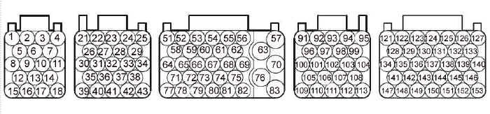
Items in red descriptions are for vehicles with automatic
transmissions only.
| Pin# | Connection | Pin# | Connection | |
|---|---|---|---|---|
| 1 | Flash EP Regulated Power
Supply? (Pin 11 OBD2 Connector) |
10 | - | |
| 2 | Evaporative Emissions Control Solenoid | 11 | - | |
| 3 | - | 12 | - | |
| 4 | Ground | 13 | - | |
| 5 | Fan Control Relay (High Speed) | 14 | Vehicle Speed Sensor | |
| 6 | Fuel Pump Relay | 15 | K-Line (Pin 7 OBD2 Connector) | |
| 7 | Ground | 16 | - | |
| 8 | - | 17 | CAN High (Pin 6 OBD2 Connector) | |
| 9 | - | 18 | CAN Low (Pin 14 OBD2 Connector) | |
| Pin# | Connection | Pin# | Connection | |
| 21 | 5 V Sensor Power Supply | 33 | - | |
| 22 | - | 34 | Body Ground | |
| 23 | Fuel Tank Differential Pressure Sensor | 35 | - | |
| 24 | - | 36 | Switch Switch (down) | |
| 25 | Body Ground | 37 | - | |
| 26 | Accelerator Pedal Input Signal (Main) | 38 | Body Ground | |
| 27 | Accelerator Pedal Input Signal (Sub) | 39 | Select Switch | |
| 28 | - | 40 | - | |
| 29 | Body Ground | 41 | Fuel Tank Temperature Sensor | |
| 30 | 5 V Power Supply To Accelerator Pedal (Main) | 42 | Back Up 12V Power Supply To ECU | |
| 31 | - | 43 | Ignition Switch Input | |
| 32 | Shift Switch (up) | |||
| Pin# | Connection | Pin# | Connection | |
| 51 | 12V Power Supply | 67 | Transmission Range Switch: P | |
| 52 | MFI Relay (Power Supply) | 68 | - | |
| 53 | Reduction Solenoid Valve | 69 | - | |
| 54 | Torque Converter Clutch Solenoid Valve | 70 | Solenoid Valve Power Supply | |
| 55 | Overdrive Solenoid Valve | 71 | - | |
| 56 | Low-Reverse Solenoid Valve | 72 | - | |
| 57 | Solenoid Valve Power Supply | 73 | Transmission Range Switch: D | |
| 58 | - | 74 | Transmission Fluid Temperature Sensor | |
| 59 | - | 75 | - | |
| 60 | - | 76 | - | |
| 61 | Transmission Range Switch: R | 77 | Transmission Range Switch: N | |
| 62 | - | 78 | Power Steering Switch | |
| 63 | - | 79 | Left Bank (Front) Heated O2 Sensor offset voltage | |
| 64 | 12V Power Supply | 80 | Right Bank (Rear) Heated O2 Sensor offset voltage | |
| 65 | Underdrive Solenoid Valve | 81 | A/C Compressor Clutch Relay | |
| 66 | Second Solenoid Valve | 82 | A/T Control Relay | |
| 83 | Starter Signal | |||
| Pin# | Connection | Pin# | Connection | |
| 91 | Left Bank Heated O2 Sensor | 103 | Crankshaft Position Sensor | |
| 92 | Right Bank Heated O2 Sensor | 104 | Camshaft Position Sensor | |
| 93 | Engine Coolant Temp Sensor | 105 | Left Bank Heated O2 Sensor (rear) Offset Voltage | |
| 94 | Power Supply Voltage Applied To TPS | 106 | Right Bank Heated O2 Sensor (rear) Offset Voltage | |
| 95 | - | 107 | Intake Air Temperature Sensor | |
| 96 | Left Bank Heated O2 Sensor (Rear) | 108 | Mass Air Flow Sensor | |
| 97 | Right Bank Heated O2 Sensor (Rear) | 109 | Right Bank Oil Pressure Sensor | |
| 98 | Throttle Position Sensor (Sub) | 110 | Left Bank Oil Pressure Sensor | |
| 99 | Throttle Position Sensor (Main) | 111 | Input Shaft Speed Sensor | |
| 100 | - | 112 | Output Shaft Speed Sensor | |
| 101 | - | 113 | - | |
| 102 | Manifold Absolute Pressure Sensor | |||
| Pin# | Connection | Pin# | Connection | |
| 121 | - | 138 | - | |
| 122 | Power Supply Voltage Applied Throttle Actuator Control Motor | 139 | No 4 Injector | |
| 123 | Throttle Actuator Control Motor Relay | 140 | No 3 Injector | |
| 124 | EGR Stepper Motor Coil B2 | 141 | - | |
| 125 | Left Bank Heated O2 Sensor (Front) | 142 | EGR Stepper Motor Coil A1 | |
| 126 | Right Bank Heated O2 Sensor (Front) | 143 | Ignition Coil-No 5 (Ignition Power Transistor) | |
| 127 | No 6 Injector | 144 | Ignition Coil-No 3 (Ignition Power Transistor) | |
| 128 | Left Bank Engine Oil Control Valve | 145 | Variable Intake Air Solenoid | |
| 129 | - | 146 | No 2 Injector | |
| 130 | EGR Stepper Motor Coil B1 | 147 | Throttle Actuator Control Motor | |
| 131 | Generator FR Terminal | 148 | Ignition Coil-No 4 (Ignition Power Transistor) | |
| 132 | Generator G Signal | 149 | Evaporative Emission Purge Solenoid | |
| 133 | No 5 Injector | 150 | Ignition Coil-No 2 (Ignition Power Transistor) | |
| 134 | Ignition Coil-No 6 (Ignition Power Transistor) | 151 | Ignition Coil-No 1 (Ignition Power Transistor) | |
| 135 | Right Bank Engine Oil Control Valve | 152 | - | |
| 136 | EGR Stepper Motor Coil A2 | 153 | No 1 injector | |
| 137 | - | |||
Contact Road///Race Engineering
13022 La Dana Ct. Santa Fe Springs, Ca. 90670 Tel (562) 777-1522 Fax (562) 777-1562Last updated 6/09mw