
Hard Failures
Hard failures cause the Check Engine light to illuminate and remain
on until the problem is repaired. If the light comes on and remains
on (light may flash) during vehicle operation, the cause of the
malfunction can be determined using the diagnostic code charts.
If a sensor fails, the computer will use a substitute value in its
calculations to attempt to continue engine operation. In this
condition, commonly known as “limp-in” mode, the vehicle
may run but drivability will be poor.
Intermittent Failures
Intermittent failures may cause the Check Engine light to flicker or
illuminate and go our after the intermittent fault goes away.
However, the corresponding code will be retained in the computer
memory. If a related fault does not reoccur within a certain time
frame, the code will be erased from the computer memory. Intermittent
failures may be caused by sensor, connector or wiring related
problems.
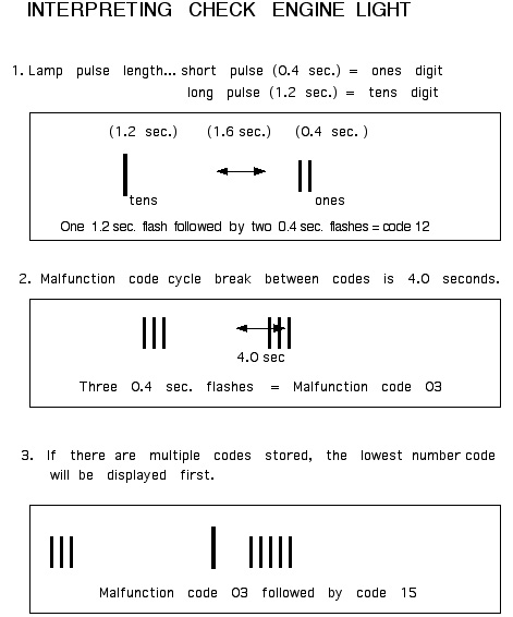
Retrieving Codes
Using the jumper wire, connect the green single connector (on the
firewall below the windshield wiper motor) to ground.
With the ignition On and engine Off, observe the check engine light.
Note any codes and record them on a piece of paper. Check the trouble
code table for possible cause(s).
If the light remains on continuously, the check engine light circuit
is grounded or the computer is defective. If the light does not
illuminate there are no trouble codes stored.
Clearing Codes
After necessary repairs have been made, disconnect the negative
battery cable. Depress the brake pedal for at least 5 seconds.
Reconnect the battery cable.
CODE 01
Computer is sensing poor or no Ignition Pulse. Check for any poor
connections at the ignition coil. The coil may be failing; measure
the resistance of the primary and secondary coils.
Primary coil resistance is measured between the two small terminals
on the coil. Resistance should be between 0.72 and 0.88 W.
Secondary coil resistance is measured between the negative terminal
(yellow/blue wire) and the high tension terminal (plug wire).
Resistance should be between 6 and 30 kW.
If the coil checks out OK, or replacing it with a known good coil
does not work, check for continuity between coil negative wire
(yellow/blue) and the computer terminal 1M. Terminal 1M is on the
top, sixth from the left (yellow/blue wire).
CODE 03
Computer is not receiving a good G Signal from the distributor. Check
the distributor connections and repair if necessary. If the
connectors check out OK, measure the voltage at terminal 1N of the
computer with the engine at idle. Terminal 1N is on the bottom, sixth
from the left (yellow wire).
If there is no voltage there may be a break in the wire between
terminal 1N and the distributor, or the G Signal generator inside the
distributor may be defective. If the voltage measures approximately
3.0 volts then the problem may be in the computer itself.
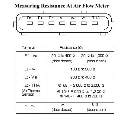
CODE 08
Computer is reading incorrect or no signal from the Air Flow Meter.
Check the large electrical connector on the Air Flow Meter for poor
connections, also check for any possible intake tract leaks. If no
problems are found, next check the resistance of the Air Flow Meter
(see chart).
CODE
09
The computer is receiving an incorrect signal from the Water Thermo
Sensor. The Water Thermo Sensor is located on the back side of the
engine below the intake manifold. It is fairly difficult to get to
(above the starter). The best way to reach it is from underneath the
car . Removing the oil filter helps . Check the connector first for
any possible bad connection. If the connection looks OK then check
the resistance of the sensor. You may need to remove the sensor to
test it (some coolant will drain out). The resistance between the two
terminals at 68 degrees should be 2.21- 2.69 kW . If the sensor is
warmed up to 176 degrees the resistance should drop to 0.290 -
0.354 kW. If the sensor fails these tests it should be replaced.
CODE 10
The computer is receiving an incorrect signal from the Intake Air
Thermo Sensor. The sensor is located inside the Air Flow Meter . Open
up the air box and look underneath the top section at the bottom of
the Air Flow Meter. This is where the Intake Air Thermo Sensor is
located. First check the connections at the Air Flow Meter. If this
checks out OK, then check the resistance of the sensor. To do this
measure the resistance between terminals E2 and THA (see chart). Heat
the sensor with a light bulb to obtain the different temperature
readings. If the sensor tests bad the Air Flow Meter must be
replaced. If the sensor tests OK then the problem is most likely in
the wiring harness.
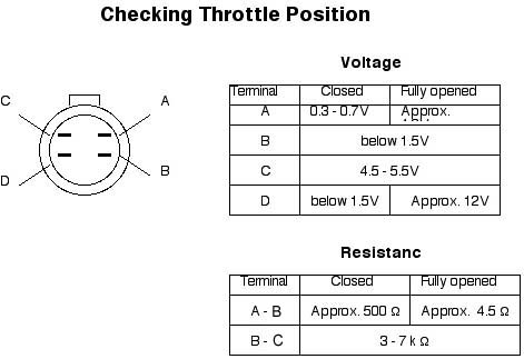
CODE 12
The computer is receiving poor information from the Throttle Position
Sensor. The first step is to check the connections at the sensor and
repair if necessary. Next check the resistance and voltage at the
Throttle Position Sensor by removing the rubber boot from the
connector and turning on the ignition. Check the voltage between each
terminal and ground (see chart). If terminal D only is incorrect the
sensor may be out of adjustment. If others are incorrect check the
resistance between the terminals (see chart).If the resistance is
incorrect the Throttle Position Sensor needs to be replaced. If
everything seems OK the problem may be in the wiring harness.
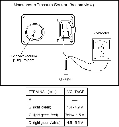
CODE 14
The computer is not receiving correct signals from the Atmospheric
Pressure Sensor. The Sensor is located on the upper firewall on the
passenger side. Locate the Sensor, remove the rubber cap, and connect
a vacuum pump to the port. Use the diagram and chart to check
the voltage between each terminal and ground while applying and
releasing vacuum to the Sensor.
If the voltage at C or D terminal is not correct, check the wiring
harness. If the voltage at terminals C and D are OK but terminal B is
wrong, the Sensor should be replaced.
CODE 15
The computer has not sensed voltage above 0.55v from the Oxygen
Sensor 120 seconds after the engine speed passed beyond 1,500 rpm.
Check the green single connector for the Oxygen Sensor at the
driver’s side end of the cylinder head. If the connector and the
wires look OK, then the problem is most likely in the Oxygen
Sensor.
To test the Oxygen Sensor, warm up the engine and let it run at idle.
Disconnect the Oxygen Sensor at the green connector and using a
digital volt meter, measure the voltage between the sensor and
ground. At idle the voltage should vary between 0.3 and 0.7 volts.
Next run the engine at 4,000rpm until the volt meter reads about 0.7
volts. Rev the engine several times while reading the volt meter. On
acceleration the voltage should be between 0.5 and 1.0 volts (rich).
On de-acceleration the voltage should drop to between 0 to 0.3 volts
(lean). If the Oxygen Sensor does not perform as listed above,
replace the sensor.
CODE 17
The Oxygen Sensor output voltage is below 0.45 volts 20 seconds after
the engine has passed 1,500rpm. This code may indicate a faulty
Oxygen Sensor (see test procedure in code 15). This code can also
indicate an over-lean condition. Check also for any possible intake
air leaks, or leaks in any vacuum hoses or emission components. Check
the spark plugs also; clean or replace if necessary.
CODE 25, 26, 27
These codes are for the three solenoid valves on the center of the
firewall. Generally an indicated fault will be caused by faulty
wiring or a poor electrical connection. If the wiring and
connections check OK then test the solenoid valve itself. Without
voltage applied to the solenoid air should not flow through the valve
from one hose port to the other. With 12volts applied to the two
terminals of the solenoid air should flow through from one hose port
to the other. If the solenoid valve fails this test, replace it.
Code 25 is the solenoid valve for the fuel pressure regulator. Of the
three valves it is the one on the driver’s side. This
valve cuts off
vacuum to the fuel pressure regulator when the engine is warm for 2
minutes after the engine is started. This temporarily raises
the fuel pressure to help prevent vapor lock.
Code 26 is the solenoid valve in the center that operates the vacuum
switch valve. Code 27 is the solenoid valve on the passenger side and
operates the no. 1 purge control valve. These two solenoids combine
to allow fumes from the fuel tank to enter the intake manifold and be
burned.
CODE 34
The computer is detecting a problem with the BAC valve. The BAC
(Bypass Air Control) valve is part of the Idle Speed Control System.
The ISC system allows metered air to bypass around the throttle plate
to maintain a steady idle. The BAC valve operates only when the
engine is cold, similar to what a choke would do on a carbureted car.
The ISC valve operates all the time to maintain a constant idle
speed. The BAC valve is located on the back side of the
intake manifold all the way to the passenger side.
The BAC valve has two large hoses running to it, one from the intake
pipe on top of the valve cover to the BAC valve and the other runs
from the BAC valve to the intake manifold. First check the electrical
connection to the BAC valve, this is the most likely spot for
trouble. If the wiring checks OK then check the operation of the BAC
valve.
The following tests are performed with the engine off. To check
the BAC valve, disconnect the air hose from the funnel-shaped air
intake pipe. Blow through the valve and check the air flow. With the
engine cold air should flow; with the engine warm, air should not
flow. To check the Idle Speed Control valve , unplug the electrical
connector to the BAC valve. Connect an ohmmeter to the terminals of
the BAC valve and check the resistance. Resistance should be between
5-20 W .